[ English | Indonesia | 한국어 (대한민국) | English (United Kingdom) | русский | français | español | Deutsch ]
Container networking
OpenStack-Ansible deploys Linux containers (LXC) and uses Linux bridging between the container and the host interfaces to ensure that all traffic from containers flows over multiple host interfaces. This appendix describes how the interfaces are connected and how traffic flows.
For more information about how the OpenStack Networking service (neutron) uses the interfaces for instance traffic, please see the OpenStack Networking Guide.
For details on the configuration of networking for your environment, please have a look at openstack_user_config settings reference.
Physical host interfaces
In a typical production environment, physical network interfaces are combined in bonded pairs for better redundancy and throughput. Avoid using two ports on the same multiport network card for the same bonded interface, because a network card failure affects both of the physical network interfaces used by the bond.
Linux bridges
The combination of containers and flexible deployment options requires implementation of advanced Linux networking features, such as bridges and namespaces.
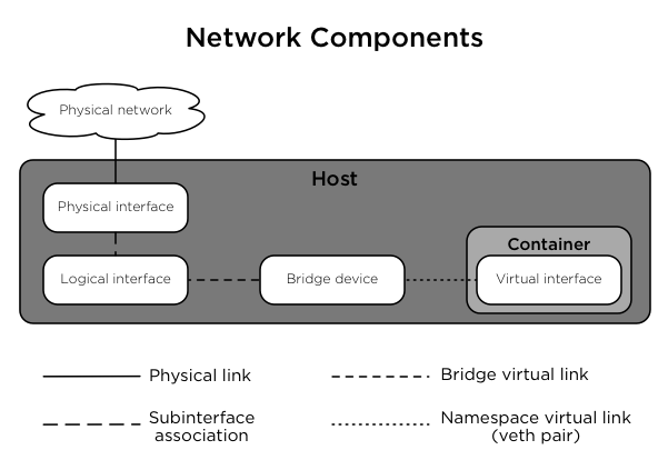
Bridges provide layer 2 connectivity (similar to switches) among physical, logical, and virtual network interfaces within a host. After a bridge is created, the network interfaces are virtually plugged in to it.
OpenStack-Ansible uses bridges to connect physical and logical network interfaces on the host to virtual network interfaces within containers.
Namespaces provide logically separate layer 3 environments (similar to routers) within a host. Namespaces use virtual interfaces to connect with other namespaces, including the host namespace. These interfaces, often called
vethpairs, are virtually plugged in between namespaces similar to patch cables connecting physical devices such as switches and routers.Each container has a namespace that connects to the host namespace with one or more
vethpairs. Unless specified, the system generates random names forvethpairs.
The following image demonstrates how the container network interfaces are connected to the host’s bridges and physical network interfaces:
Network diagrams
Hosts with services running in containers
The following diagram shows how all of the interfaces and bridges interconnect to provide network connectivity to the OpenStack deployment:
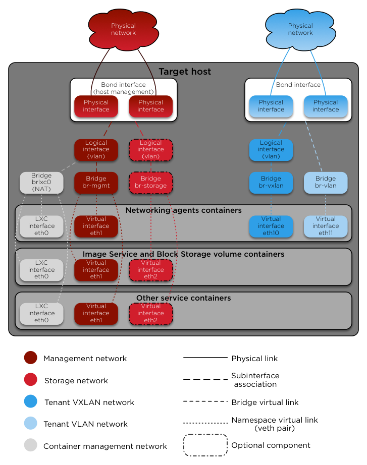
The interface lxcbr0 provides connectivity for the containers to the
outside world, thanks to dnsmasq (dhcp/dns) + NAT.
Примечание
If you require additional network configuration for your container interfaces
(like changing the routes on eth1 for routes on the management network),
please adapt your openstack_user_config.yml file.
See openstack_user_config settings reference for more details.
Services running «on metal» (deploying directly on the physical hosts)
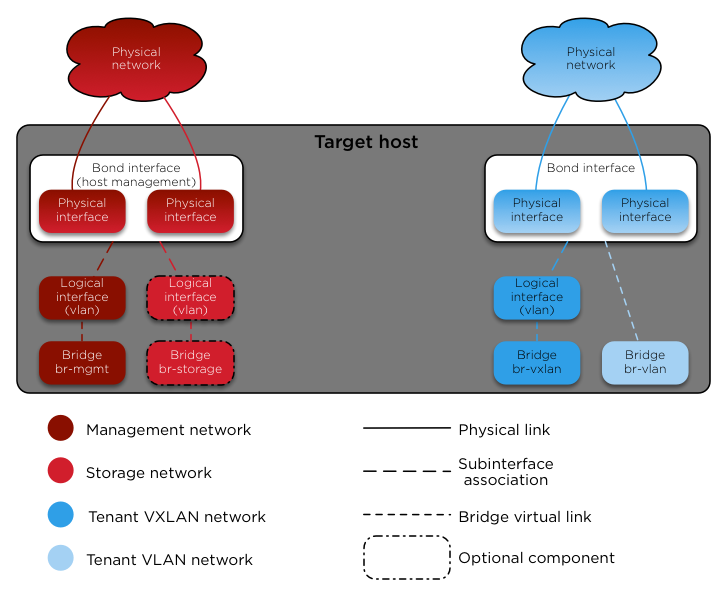
OpenStack-Ansible deploys the Compute service on the physical host rather than in a container. The following diagram shows how to use bridges for network connectivity:
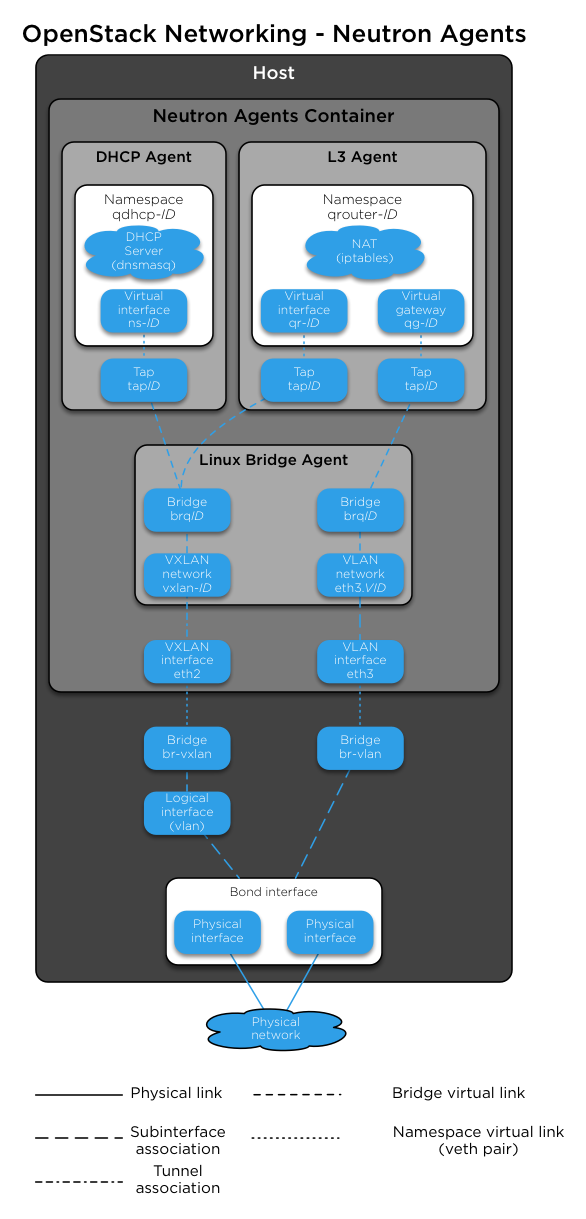
Neutron traffic
The following diagram shows how the Networking service (neutron) agents
work with the br-vlan and br-vxlan bridges. Neutron is configured to
use a DHCP agent, an L3 agent, and a Linux Bridge agent within a
networking-agents container. The diagram shows how DHCP agents provide
information (IP addresses and DNS servers) to the instances, and how routing
works on the image.
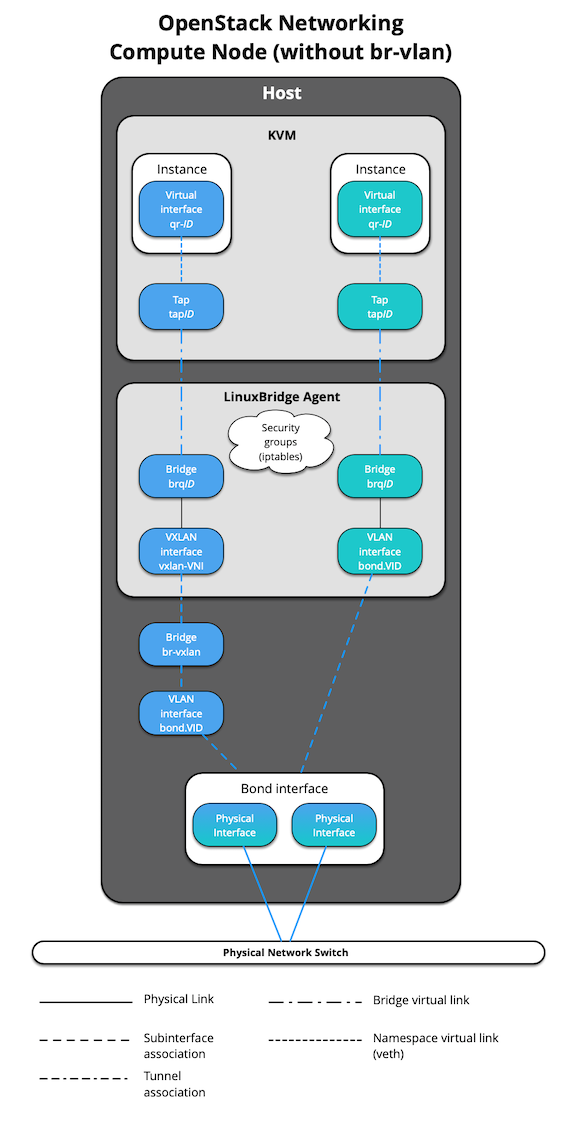
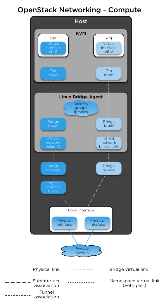
The following diagram shows how virtual machines connect to the br-vlan and
br-vxlan bridges and send traffic to the network outside the host:
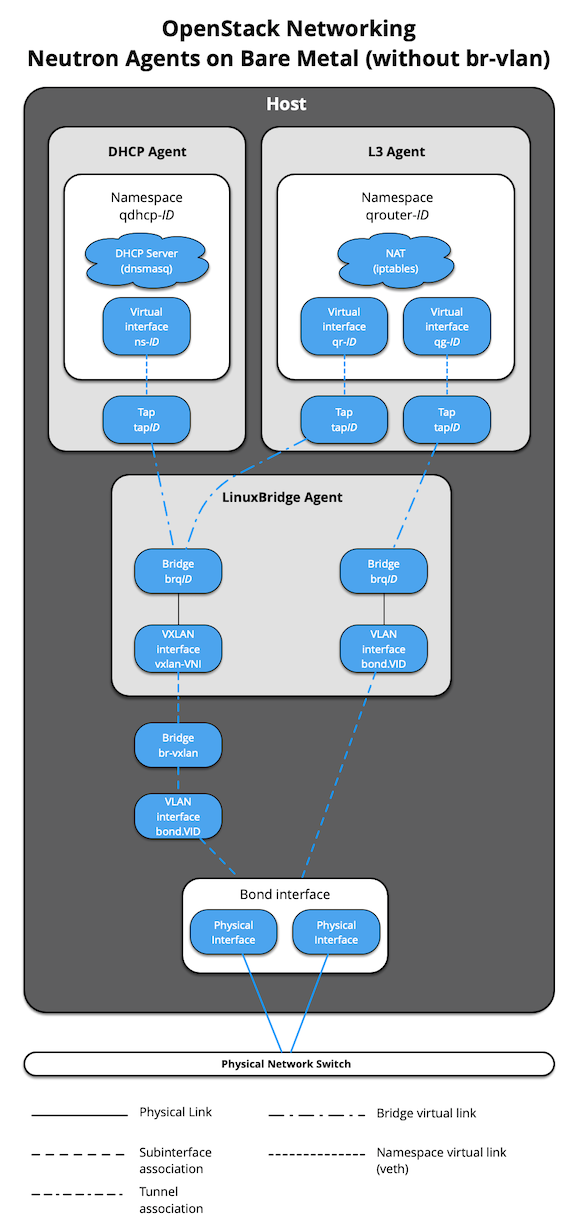
When Neutron agents are deployed «on metal» on a network node or collapsed
infra/network node, the Neutron Agents container and respective virtual
interfaces are no longer implemented. In addition, use of the
host_bind_override override when defining provider networks allows
Neutron to interface directly with a physical interface or bond instead of the
br-vlan bridge. The following diagram reflects the differences in the
virtual network layout.
The absence of br-vlan in-path of instance traffic is also reflected on
compute nodes, as shown in the following diagram.
